

Specifications
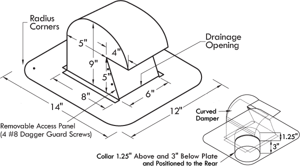
Every DryerJack® is built tough right here in the U.S. By design, the extra clearance model 486 is airflow efficient, and deters pest entry. It includes a removable access door for easy duct cleaning- Rugged 26 Gauge Galvalume ®
- Complies With IMC 504.4 & IRC 1502.3
- Flange Includes Nail Holes for Fast Installation
- Flange has Rounded Flange Corners for Easier Handling
- Built-in 4" Water-tight Collar Protrudes 1.25" into Hood 3" into Duct
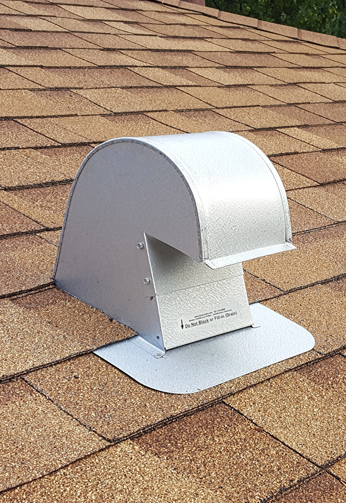 DryerJack Model DJK486 through a Slightly Sloped Roof
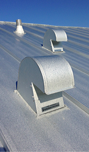 Galvalume Roof Vent Installation
Special Requirements
DryerJacks are optimally designed for roof pitch between 3/12 and 12/12. Select Model 486U with an integrated curb cover to deliver maximum weather protection for flat roof installations (less than 3/12 pitched roof). Roof pitch in excess of 45 degrees will render the damper ineffective.
)
Installation Instructions
- Tools Needed
- Tape Measure
- Flat Pry Bar
- Caulk Gun
- Reciprocating Saw
- Battery Powered Drill
- Hammer
- Material Needed
- Leather Gloves
- DryerJack Model - 486
- Silver Foil Tape
- Roofing Cement (1-2 tubes)
- Galvanized Screws or Nails
GENERAL: Before installation, ensure that the substrate is uniform and even. Installation shall be made in accordance with recognized sheet metal practices. SMACNA Architectural Sheet Metal Manual 6th Ed. Specifications shall be used as a guide and basis for detail whenever applicable.
NOTE: Recommended use of this product is for exhaust of warm dry or slightly moist air only. This product is not intended for venting of exhaust grease or liquid.
Sloped Roof Installation- Dry-fit the duct work assembly that will run from the dryer to the roof. Draw a circle around the perimeter of the duct work onto the underside of the roof sheathing.
- Drive a nail upward through the roof, from the inside to mark the center location of the vent.
- Access the roof and locate the nail (where the shingles are lifted up slightly is an indication). Cut a hole slightly larger than the duct pipe of the hood with a reciprocating saw.
- Place the vent hood into position and trace the outline of the flashing so you know the areas where you need to lift the shingles to get the flashing underneath.
- Lift the shingles on the sides and top of the hole where the flashing will go with a flat bar. Remove the nails that hold those shingles in place by carefully sliding the flat bar between the shingles and the roof sheathing.
- Dry-fit the vent to confirm adequate shingle lifting and removal is sufficient. Remove vent and apply liberally roofing cement to the areas of the roof and vent where they come in contact with each other. Install vent, mechanically fasten the flashing plate to the roof deck using nails or stainless steel screws in predrilled holes where possible, making sure the top edge of the flashing is underneath the loosened shingles on the top and sides of the vent so the shingles overlap the edge of the flashing. This helps prevent water from seeping underneath the flashing.
- Allow the front part of the flange to lie over the shingles (so water runs down). Apply roofing cement or roofing silicone caulk around the edges of the flashing (DO NOT fill or block the drainage slot on the low side of the vent) as well as a “smear” on each nail head.
- Apply roofing cement to the underside of the detached shingles. Apply the roofing cement only to the shingles covering the back and sides of the roof vent's flange.
New FLAT ROOF Installation (Model DJK486U Only).
GENERAL: Not recommended for very heavy snowfall regions without 8" or greater curb.
Not recommended for hydrostatic roof systems (waterproof and able to hold water) unless a 6" or higher curb is incorporated.
Minimum recommended slope is 1:.250" (quarter inch per foot) with positive drainage confirmed and no potential for ponding greater than ¾ inch.
- Assuming the above conditions are met, dry-fit the duct work assembly that will run from the dryer to the roof. Draw a circle around the perimeter of the duct work onto the underside of the roof sheathing.
- Drive a nail through the roof and tapered insulation to assist in marking the location of the vent on the topside.
- Access the roof and locate the nail. Cut a hole slightly larger than the duct pipe of the hood with a reciprocating saw.
- Place the vent hood into position and mechanically fasten the flashing plate to the roof deck using nails or stainless steel in predrilled holes where possible. Apply roofing felt, flashing and modified bitumen per local standards making sure to not block drain slot in roof vent.
Existing Silver Coated Roof
- Assuming the General Conditions are met, dry-fit the duct work assembly that will run from the dryer to the roof. Draw a circle around the perimeter of the duct work onto the underside of the roof sheathing.
- Drive a nail through the roof and tapered insulation to assist in marking the location of the vent on the topside.
- Access the roof and locate the nail. Cut a hole slightly larger than the duct pipe of the hood with a reciprocating saw. Mechanically fasten the flashing plate to the roof deck using nails or screws.
- Prime the area around the vent approximately 6-8" onto the field of the roof. This is necessary due to the existing silver coat.
- Allow the primer to cure and flame-prime the same area and allow that to cool and prime the metal flange.
- Apply the modified bitumen and roofing cement per local standards taking caution to not block the drain slot in the metal vent.
- Silver coat the exposed asphalt modified bitumen.